
introduction
A Conduit Fill Chart is an important reference tool used by electricians, electrical contractors, engineers, inspectors, and DIY users to determine how many wires can safely fit inside a particular conduit. Choosing the correct conduit size is not simply a matter of making sure the wires physically fit. Electrical codes place limits on the amount of space that conductors can occupy inside a raceway.
A properly selected conduit provides enough room for conductors to be installed without excessive crowding, insulation damage, or difficult pulling conditions. For electrical installations based on the National Electrical Code (NEC), conduit-fill calculations are primarily associated with NEC Chapter 9 and its tables.
This guide explains what a conduit fill chart means, how the major fill percentages work, how conductor and conduit areas are determined, and how to approach a basic conduit fill calculation.
What Is a Conduit Fill Chart?
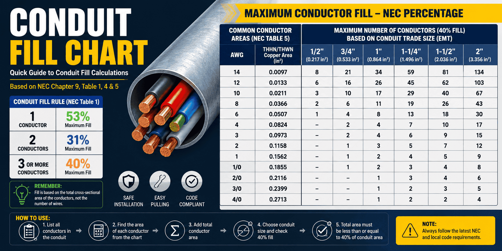
A conduit fill chart is a reference that helps determine the maximum amount of conductor area that can occupy a conduit or raceway. Instead of measuring every wire and conduit manually, electricians can use standardized tables to compare conductor sizes with available conduit space.
The calculation is based on area, not simply the number of wires. Two wires of different sizes can occupy very different amounts of space, even if both are counted as two conductors.
For NEC-based installations, three important references are commonly involved:
- Chapter 9, Table 1 – establishes maximum conduit fill percentages.
- Chapter 9, Table 4 – provides conduit and tubing dimensions and internal areas.
- Chapter 9, Table 5 – provides approximate cross-sectional areas for insulated conductors.
Together, these references provide the foundation for many conduit-fill calculations.
Why Is Conduit Fill Important?
Conduit is designed to protect electrical conductors and provide an organized pathway for wiring. However, filling a raceway too heavily can create installation and maintenance problems.
A conduit that is technically large enough to contain the wires still needs sufficient space for the conductors to be pulled through the raceway. Excessive crowding can increase friction and make installation more difficult.
Conduit fill requirements also work alongside other electrical requirements. Passing a conduit-fill calculation does not automatically mean that an entire electrical installation complies with every applicable code requirement.
For example, conductor ampacity, temperature limitations, conductor grouping, voltage drop, bending requirements, grounding, and local amendments may require separate evaluation.
That is why a conduit fill chart should be viewed as one part of the overall electrical design process rather than a complete electrical-sizing solution.
The 53%, 31%, and 40% Conduit Fill Rules
One of the most important concepts to understand is the maximum fill percentage based on the number of conductors.
Under the commonly referenced NEC Chapter 9, Table 1 limits are:
| Number of Conductors | Maximum Fill |
| 1 conductor | 53% |
| 2 conductors | 31% |
| 3 or more conductors | 40% |
The 40% limit for three or more conductors is the value encountered most frequently in typical multi-conductor conduit calculations.
There is also a special provision for certain short raceway sections, commonly called nipples, where the permitted fill can be higher under the applicable NEC conditions. Current references identify a 60% allowance for a nipple 24 inches or less between enclosures.
These percentages apply to the conductor area relative to the conduit’s internal cross-sectional area.
Why Does the Fill Percentage Change?
At first glance, it may seem strange that one conductor can occupy 53%, two conductors only 31%, and three or more conductors 40%.
The reason is related to how conductors physically occupy a round raceway. A single conductor can move through a conduit without the same interaction that occurs when multiple conductors are pulled together.
Two conductors can create an arrangement that makes pulling more difficult, while three or more conductors tend to form a more predictable bundle. The NEC therefore uses different area limits for these situations.
The important point for practical calculations is simple:
Do not automatically use 40% for every conduit-fill calculation. First determine how many conductors are involved and then apply the appropriate fill percentage.
Understanding Conductor Area
A common mistake is to calculate conduit fill using only the diameter of the copper or aluminum conductor.
For insulated wire, the insulation also occupies space. Therefore, conduit-fill calculations use the appropriate conductor cross-sectional area rather than simply using the bare metal conductor size.
For example, commonly referenced NEC Table 5 values include approximately:
| Conductor | Approx. THHN Area |
| #14 AWG | 0.0097 in² |
| #12 AWG | 0.0133 in² |
| #10 AWG | 0.0211 in² |
| #8 AWG | 0.0366 in² |
| #6 AWG | 0.0507 in² |
| #4 AWG | 0.0824 in² |
| #3 AWG | 0.0973 in² |
| #2 AWG | 0.1158 in² |
| #1 AWG | 0.1562 in² |
| 1/0 AWG | 0.1855 in² |
These values demonstrate why simply counting conductors is not enough. A conduit containing several large conductors may reach its fill limit much sooner than one containing the same number of smaller conductors.
Actual conductor area should always be taken from the applicable code table for the specific conductor type and insulation.
Understanding Conduit Area
After determining the total area occupied by the conductors, the next step is to determine the internal area of the selected conduit.
NEC Chapter 9, Table 4 provides information for different raceway types and trade sizes. Conduit types can include:
- EMT
- IMC
- RMC
- PVC
- FMC
- LFMC
- Other recognized raceway types
The same trade size does not necessarily have exactly the same internal area across different conduit types.
For example, a 1/2-inch EMT and a 1/2-inch PVC conduit should not automatically be assumed to have identical usable internal areas. The correct value must be taken from the applicable table for the specific raceway.
This is one reason a professional conduit fill chart often separates conduit types instead of providing one universal wire-count number.
How to Calculate Conduit Fill
The basic calculation can be broken into a few straightforward steps.
Step 1: Identify the Conductors
List every conductor that will be installed in the conduit.
For example, a project might contain:
- Three #12 THHN conductors
- One equipment grounding conductor
Do not ignore the grounding conductor when determining raceway fill. Applicable NEC provisions require grounding conductors to be considered in conduit-fill calculations.
Step 2: Find the Area of Each Conductor
Use the appropriate conductor table to determine the cross-sectional area of each wire.
Suppose three #12 THHN conductors each have an area of approximately 0.0133 square inches.
The conductor area would be:
3 × 0.0133 = 0.0399 in²
If another conductor is present, its area must also be added.
Step 3: Add the Areas Together
The total conductor area is the sum of all individual conductor areas.
For mixed wire sizes, calculate each group separately before adding the results.
For example:
4 × #12 THHN = 4 × 0.0133 = 0.0532 in²
Then add the area of the grounding conductor or any other conductor included in the raceway.
Step 4: Determine the Applicable Fill Percentage
Count the conductors and select the applicable fill limit.
For three or more conductors, the commonly applicable limit is 40%.
Step 5: Check the Conduit Area
Find the internal area of the selected conduit using the applicable conduit table.
The allowable conductor area can then be determined by applying the appropriate fill percentage.
For example, if a conduit has an internal area of 0.533 in² and the applicable limit is 40%:
0.533 × 0.40 = 0.2132 in²
Therefore, approximately 0.2132 square inches is the maximum conductor area under that 40% calculation.
Step 6: Compare the Results
Finally, compare the total conductor area with the allowable area.
If the conductor area is less than or equal to the applicable allowable area, the raceway passes the basic fill calculation.
If the conductor area exceeds the allowable area, a larger conduit or a different installation arrangement may be required.
Example of a Conduit Fill Calculation
Consider a simple example involving three #12 THHN conductors in 3/4-inch EMT.
Each #12 THHN conductor has an approximate area of 0.0133 square inches.
Total conductor area:
3 × 0.0133 = 0.0399 in²
For three conductors, use the 40% fill limit.
A commonly referenced 3/4-inch EMT internal area is approximately 0.533 square inches, giving a 40% allowable area of about:
0.533 × 0.40 = 0.2132 in²
The conductor area of 0.0399 in² is substantially below 0.2132 in².
Therefore, the basic conduit-fill calculation passes.
This example illustrates an important principle: conduit fill is an area comparison, not just a wire-count comparison.
Conduit Fill Chart vs. Conductor Ampacity
Conduit fill and conductor ampacity are two different calculations.
Conduit fill asks:
Do the conductors occupy an acceptable amount of space inside the raceway?
Ampacity asks:
Can the conductor safely carry the required electrical current under the applicable conditions?
A conduit can pass a fill calculation while the wiring still requires an ampacity adjustment or another electrical design check.
For example, when multiple current-carrying conductors are installed together, conductor ampacity may need adjustment under the applicable NEC requirements. This is separate from the physical space calculation.
Therefore, never use a conduit fill chart as a substitute for wire-sizing or ampacity calculations.
Common Conduit Fill Mistakes
1. Counting Wires Without Considering Their Size
Ten small wires do not occupy the same area as ten large wires.
Always calculate conductor area.
2. Ignoring Insulation
The space occupied by insulated wire includes the insulation, not just the metal conductor.
3. Using the Wrong Conduit Type
Different raceways can have different internal dimensions.
Always select the correct table entry.
4. Forgetting the Grounding Conductor
Grounding conductors can count toward conduit fill. They should not automatically be excluded from the calculation.
5. Assuming 40% Applies Everywhere
The number of conductors determines the applicable fill percentage. The commonly used limits are 53%, 31%, and 40%, depending on conductor count.
6. Treating Fill as the Only Requirement
A successful fill calculation does not prove that the complete electrical installation meets every applicable requirement.
Conduit Fill and Different Wire Types
Conductor insulation affects the amount of space a wire occupies. This is why a conduit fill chart should identify the wire type rather than simply saying something like “#12 wire.”
THHN, THWN, XHHW, and other conductor constructions can have different outside dimensions and therefore different cross-sectional areas.
When calculating fill, use the appropriate conductor-area value for the actual wire being installed.
This is especially important in projects involving mixed conductor types or larger commercial installations.
Why Conduit Fill Charts Are Useful
A well-designed conduit fill chart saves time and reduces calculation errors.
Instead of repeatedly performing calculations from scratch, an electrician can quickly locate:
- The conductor type
- The conductor size
- The number of conductors
- The conduit type
- The conduit trade size
- The applicable fill percentage
A digital conduit fill calculator can make this even faster by automatically adding conductor areas and comparing the result with the allowable conduit capacity.
However, the underlying code requirements should still be understood. A calculator is a convenience; it should not replace knowledge of the applicable electrical code.
Conduit Fill Chart for Quick Reference
The following simplified chart provides a useful starting point:
| Conductors in Raceway | Maximum Fill |
| 1 | 53% |
| 2 | 31% |
| 3 or more | 40% |
| Short nipple, applicable condition | Up to 60% |
The actual number of wires that can fit depends on the conductor size, insulation, conduit type, conduit trade size, and applicable code provisions.
Tips for Choosing the Right Conduit Size
When selecting conduit, it is usually better to calculate the requirement before beginning installation rather than trying to force a crowded wire bundle through an undersized raceway.
A few practical principles can help:
- Identify all conductors before selecting conduit.
- Use the actual conductor type and insulation.
- Calculate the total conductor area.
- Apply the correct fill percentage.
- Check the internal area of the exact conduit type.
- Consider grounding conductors.
- Check other electrical requirements separately.
- Account for local code amendments and inspection requirements.
- Avoid relying on a generic wire-count chart when conductor types differ.
A larger conduit can also make future maintenance and pulling work easier, although the final selection should be based on the project’s requirements and applicable code.
Conclusion
A Conduit Fill Chart is a practical reference for determining how much wiring can be installed inside a particular raceway. The most important concept is that conduit fill is based on cross-sectional area rather than simply the number of wires.
For NEC-based installations, Chapter 9 provides the primary framework: Table 1 establishes the allowable fill percentages, Table 4 provides conduit areas, and Table 5 provides conductor areas. The familiar 53%, 31%, and 40% limits provide the starting point for many calculations.